DESCRIPTION AND OPERATION
1. General
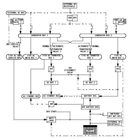
A. The electrical power system consists of 28-volt dc, 28-volt ac, and 115-volt ac systems.
B. AC Electrical Power
(1) Three isolated generators supply 115/200-volt, 3-phase, 400-Hz
power. These generators are the primary sources of power for the
main ac buses and the whole electrical power system. Two generators
are driven by the engines and one generator is driven by the
auxiliary power unit (APU).
(2) External power, provided via the external power receptacle, supplies
115/200-volt, 3-phase, 400-Hz power.
(3) Transformers provide power to the 28-volt ac buses by reducing
115-volt ac power to 28-volt ac power. Transformers are on shields
J4 and J5.
(4) A static inverter converts 28-volt dc battery power to 115-volt ac
power. It supplies the flight critical loads on the ac standby bus
when the primary power sources are off. The static inverter is in
the electronics compartment on the electrical equipment shelf.
C. DC Electrical Power
(1) Three transformer-rectifier (T-R) units provide 28-volt dc power by
converting 115-volt ac power to 28-volt dc power. T-R units are on
electrical equipment shelf E3-1.
(2) A battery provides 28-volt dc power to start the APU. Loads on the
battery bus are powered by the battery when other power sources are
de-energized. The battery is in electrical equipment area near the
electrical equipment shelves.