DESCRIPTION AND OPERATION
1. General
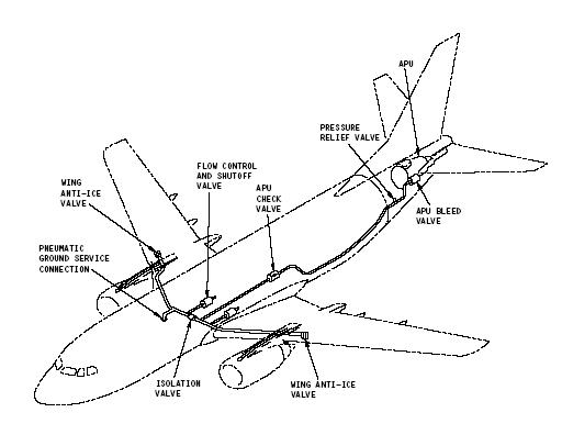
A. The purpose of the pneumatic system is to supply bleed air from the 5th and 9th stage of the engine compressor or from the APU or from a ground cart. Air is distributed by a pneumatic manifold from the above sources to the air conditioning packs, wing and cowl Thermal Anti-Ice (TAI) systems, the engine starting system, potable water system and the hydraulic reservoir. The systems using air from the pneumatic manifold are covered in their respective chapters.
B. The main supply of bleed air to the manifold is obtained from the engine 5th stage compressor. 5th stage air is supplied to the pneumatic manifold at all times except at engine idle or at low engine thrust settings. When this occurs 9th stage bleed air is automatically used.Air from the 5th and 9th stage bleed ports is controlled by the engine bleed control system . APU bleed air or pneumatic ground cart bleed air is primarily used for engine starting and for air conditioning pack operation on the ground. The APU can be used as an alternate bleed air source up to airplane altitudes of 17,000 ft.
C. The pneumatic manifold interconnects the engine bleed system and APU and distributes bleed air to the systems outlined in paragraph A. The pneumatic manifold contains the necessary valves to shut off bleed air at each engine, APU and to isolate the left and right hand systems.
D. Each engine bleed system contains a bleed air temperature control sub-system. This consists of a precooler, precooler control valve and precooler control valve sensor. The engine bleed air temperature is automatically controlled to a preset temperature whenever the engine is operating and the Pressure Regulator and Shutoff Valve (PRSOV) is open.The temperature is sensed in the precooler bleed air discharge. The sensor will cause the precooler control valve to modulate open/closed as required to maintain this temperature. Engine fan air is used as the heat sink for the bleed air.
E. Two pressure transmitters are provided for pressure indication of the bleed air. One transmitter is used for each engine. Both pressure transmitters are connected to a dual pressure indicator on the overhead panel. The engine bleed air overtemperature indication consists of overtemperature switches in the ducting system, which are connected to the overhead panel trip lights. The temperature switches illuminate the trip lights and the corresponding engine PRSOV closes when the bleed air temperature exceeds approximately 490F. Also, the bleed trip light will illuminate if there is excessive pressure at the bleed valve inlet.The engine bleed air is used to aspirate the total air temperature (TAT)probe when the airplane is on the ground or in flight with the flaps extended. The aspirator causes airflow past the sensing element to provide reliable temperature indication during ground operation. The aspirated TAT probe compensates for the heating effects of bright sunlight or hot ramp heat radiation. TAT probe deicing is provided by an hermetically sealed, coaxial type electrical heating element. Pneumatic system air for TAT probe aspiration is bled off downstream of the turbofan control valve. Make sure the valves are installed downstream of each turbofan drive air duct to prevent bleed air loss through a non-operating turbofan.
G. The high-stage manifold duct on the engine has a bleed air pressure tap provision to supply pneumatic pressure to airplanes equipped with potable water engine pressurization system.