1. General
A. The fuel system stores fuel and delivers fuel to the engines and APU.
Additional components and controls in the system provide rapid fueling
and defueling capabilities. The tanks, lines, fittings, and operating
components in the system are compatible with all fuels meeting the engine
and APU manufacturer's specifications.
B. Fuel is stored within vented areas of the wings and wing center section
and within an auxiliary fuel tank (if installed) in the aft cargo
compartment. The main fuel storage area is divided into three integral
fuel tanks: a three-cavity center tank and two wing tanks (tanks No. 1
and 2). The integral tanks utilize a sealed-wing structure to retain the
fuel. The auxiliary fuel tank (if installed) consists of a removable
fuel (bladder) cell installed inside a vapor tight lightweight aluminum
honeycomb structure. The center tank and auxiliary tank have a secondary
fuel barrier coating on the tank exterior for additional protection
against fuel leaks into pressurized areas of the airplane.
C. Fuel is loaded on airplane from a ground source through a fueling
receptacle in the pressure fueling station. The tanks can be filled
simultaneously or separately. Fuel can also be loaded into tanks No. 1
and 2 through overwing fueling ports.
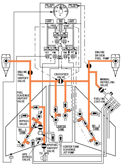
D. Electric motor-driven boost pumps and fuel lines deliver fuel from any
tank to one or both engines. Electrically-operated valves control fuel
crossfeed and engine fuel shutoff. Pump and valve controls, along with
instruments and indicating lights for monitoring the system, are arranged
on a system control panel located on the forward overhead panel.
E. Fuel from boost pumps can also be delivered through a defueling valve
into fueling manifold for removal from the airplane.
F. Fuel scavenge pumps energize after the center tank is emptied by boost
pumps during defueling or engine fuel feed. The scavenge pumps reduce
the quantity of unusable fuel in the center tank.
G. Fuel quantity indicators, in the flight compartment, and fueling quantity
indicators, at the pressure fueling station, indicate the quantity of
fuel on the airplane. Measuring sticks, installed on the underside of
each integral tank, can also be used to determine fuel quantity.
H. Fuel feed low pressure indicating lights, on the forward overhead panel,
indicate low engine boost pump outlet pressure.
I. A fuel temperature indicator, on the forward overhead panel, indicates
fuel temperature in tank No. 1.
J. Fuel is delivered to the APU from tank No. 1 either through an
independent fuel inlet or through a connection to the engine fuel feed
system. The engine ac boost pumps can be used to pressurize the APU fuel
feed system. A check valve in each inlet line prevents reverse flow
through the inactive inlet line. An electrically-operated shutoff valve,
downstream from the inlet tee, prevents pressurization of the APU fuel
line during APU shutdown.