1. General
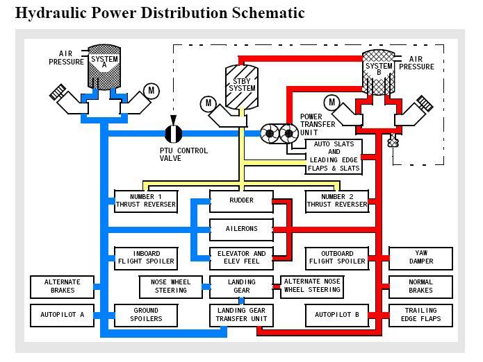
A. Three separate hydraulic systems provide fluid at 3000 psi to operate the airplane systems shown in figure 1. The hydraulic systems are identified as system A, system B and standby.
B. The standby hydraulic system provides reserve power for critical systems.
C. A ground servicing system fills all hydraulic reservoirs from one location.
D. The indicating systems provide information for crew monitoring of the
operating conditions of each hydraulic system.
2. Main Hydraulic Systems
A. The A and B system components are located on each engine and within the main gear wheel well forward section. The pressure source for each of the A and B systems consists of one engine driven pump (EDP) and one electric motor driven pump (EMDP). The EDP is directly coupled to the engine accessory gearbox and runs all the time that the engine is
running. When an ELEC pump switch is ON, the respective EMDP runs all the time.
B. Each hydraulic system has a fluid reservoir which is pressurized by air from the pneumatic system. Filter modules clean the fluid after being pressurized or after passing through the pump case drain and after returning from user systems. Heat exchangers in the fuel tanks cool the pump case drain fluid before it returns to the reservoir.
C. Ground hydraulic power connections are provided on the aft bulkhead of the left and right air conditioning bays.
3. Standby Hydraulic System
A. The standby system components are located on the keel beam in the main gear wheel well. The pressure source for the standby system is an eletric motor driven pump (EMDP). The standby EMDP is turned on automatically if system A or B fails during takeoff or landing, or it can be turned on manually by operating the FLT CONTROL A, FLT CONTROL B, or
the ALTERNATE FLAPS switches on the overhead flight control panel P5.
4. Power Transfer Unit
A. The power transfer unit (PTU) is located on the keel beam just forward of the standby reservoir. The PTU operates if system B EDP pressure is lost, flaps are not up but less than 15° and airplane is in the air. The PTU consists of a hydraulic motor connected to a hydraulic pump. The motor is driven by system A hydraulic pressure and the pump supplies pressure to the leading edge devices using system B hydraulic fluid.
There is no fluid interchange between the A and B hydraulic systems.
5. Ground Servicing System
A. A central ground servicing station is located in the right main gear wheel well on the lower outboard forward bulkhead. Hydraulic fluid is added to the reservoirs of all three systems from this station. A fill valve selects which reservoir(s) will receive fluid. Port A selects system A reservoir. Port B selects the standby and system B reservoirs. Quantity indicators at systems A and B reservoirs show fluid level. Fluid can be added under pressure from a ground service cart or with the
manual fill pump installed at the servicing station.
6. Indicating Systems
A. The indicating system consists of warning lights and gages located in the wheel well and on cockpit panels. Fluid pressure, temperature (overheat) and reservoir quantity are monitored in the cockpit while reservoir quantity and pressure are indicated in the wheel well.